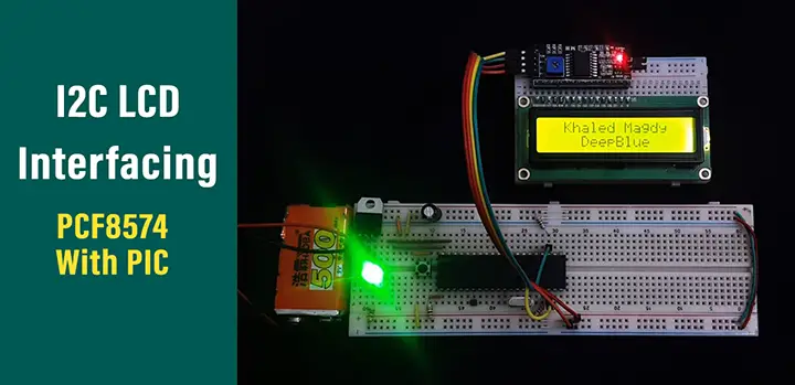

If you don’t know how to interface LCD with PIC16F877A microcontroller, read this post: In this circuit, we connected a 16×2 LCD with PIC16F877A and used the CCPI module to get an output signal ( from RC2 pin). In this example, we will see how to generate a fix duty cycle PWM signal using PIC16F877A microcontroller. Generate Fix Duty Cycle PWM using PIC16F877A

The input parameter to this function is a duty cycle. PWMx_Set_Duty() function defines the duty cycle of PWM. PWM2_Init(5000) //initialize CCP2 module with frequency 5kHz PWM1_Init(5000) //initialize CCP1 module with frequency 5kHz For instance, PIC16F877A microcontroller has two CCP modules CCP1 and CCP2.įor example, we want to use CCP1 module andwant set frequency of 5000Hz or 5KHz. Because some pic microcontrollers come in more than one CCP modules. The input parameter to this function is required frequency. Here x denotes the number of CCP module. PWMx_Init(long frequency) function used to set/declare frequency of signal. These are the four functions that are used to generate PWM, set frequency and change duty cycle.
Mplab xc8 lcd library series#
This library is generic and can be used with all PIC16F, PIC18 series microcontrollers. MikroC for PIC provides built-in libraries for to generate PWM with variables frequency and variable duty cycle.Īs mentioned earlier, MikroC provides a built-in library for pulse width modulation module of pic microcontroller. There are two CCP modules present in PIC16F877A CCP1 and CCP2 at pins RC2 and RC1 respectively. To generate PWM with the help of a PIC16F877A microcontroller, built-in CCP modules are used.

First let’s begin with MikroC for PIC compiler. As mentioned earlier, we will discuss an example with two compilers, namely, MPLAB XC8 and MikroC Pro. Now let’s start understanding how to generate different frequency and duty cycle digital signals using PIC16F877A microcontroller.Īlthough, we use PIC16F877A in this post, but you can easily apply the same concepts and examples to other PIC microcontrollers also. Now you know the basics of pulse width modulation and you also know its related terminology. Before using PWM module of Pic microcontroller, we should define the frequency/timer period of the signal. For example, a frequency of 1000Hz would mean 1000 cycles completed per second. The frequency determines the amount of time taken by PWM to complete one cycle. Similarly, if a signal stays high for a longer period of time than it stays low, the signal will have a duty cycle greater than 50%. For example, if a digital signal is on for half of the time duration and off for the other half, the digital signal is said to have a duty cycle of 50%. An on-time is the duration of a signal for which the signal stays HIGH. There are two major components of a PWM signal that defines its behavior PWM duty cycle, time period and frequency. PWM (Pulse Width Modulation) is a powerful technique used to control analog circuits with the digital output from the microcontroller.
Mplab xc8 lcd library code#

Variable Duty Cycle PWM using PIC Microcontroller.Generate Fix Duty Cycle PWM using PIC16F877A.


 0 kommentar(er)
